


Views: 13 Author: Site Editor Publish Time: 2026-05-19 Origin: Site
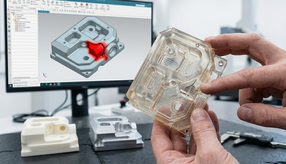
Holding a newly delivered prototype that warps, breaks, or simply refuses to fit together is a deeply frustrating experience for any hardware engineer. However, a prototype failure is rarely the end of the road; rather, it is a crucial diagnostic tool. In the world of hardware development, a failed prototype is almost never the result of a single catastrophic error. Instead, it is usually the culmination of misalignments between digital design intent and physical manufacturing realities.
If you are currently analyzing a broken component, the most pressing question is: Was the design flawed, or did the manufacturer use the wrong process? Recognizing the difference between design-induced errors and prototype manufacturing issues is the key to escaping the cycle of endless revisions.
This comprehensive guide will break down the root causes of common prototyping failures, explore how to identify the source of the problem, and outline the exact steps you need to take to iterate successfully and rescue your project timeline.
How Does Choosing the Wrong Manufacturing Process Cause Failure?
Design vs. Manufacturing: How to Tell Where the Problem Lies?
Case Study: How Did a Hardware Startup Fix Their Broken Enclosures?
Why is DFM Analysis the Ultimate Tool to Prevent Prototyping Issues?
How Can Multi-Process Iteration and Low-Volume Runs Save Your Project?
Many rapid prototyping problems begin before a single machine is ever turned on. Engineers naturally design in a pristine, frictionless digital environment (CAD). However, when those perfect geometric models are subjected to real-world physics and tooling constraints, they often fail.
The most prevalent design-level issues include:
Unreasonable Tolerances: Applying blanket "tight tolerances" (e.g., ±0.01mm) across an entire part, even on non-mating surfaces, can lead to severe machining complications and increased costs. Conversely, applying loose tolerances to critical mating joints guarantees assembly interference.
Ignoring Wall Thickness Rules: Designing walls that are too thin will lead to deformation, warping, or tearing during CNC machining and 3D printing. Walls that are too thick can cause sink marks and uneven cooling in vacuum casting or injection molding.
Un-Machinable Features: Designing perfectly sharp internal corners is a classic design flaw. CNC end mills are cylindrical and inherently leave a radius. Deep, narrow cavities that a tool cannot reach also result in impossible machining scenarios.
Material Blindness: Designing a snap-fit joint without accounting for the specific tensile strength and elasticity of the intended prototyping material guarantees the joint will snap upon first use.
On the other side of the equation, the manufacturer holds responsibility for process application. Many prototyping issues China or elsewhere arise because a supplier has limited capabilities and tries to force your design into their only available process.
Process-related failures usually manifest when the method does not align with the prototype's end-use:
Over-reliance on 3D Printing for Functional Parts: Standard SLA or FDM 3D printing is excellent for visual models, but resins and standard filaments are often anisotropic (weak across the Z-axis) and brittle. Using them for load-bearing functional testing inevitably leads to structural failure.
Wrong Process for Low-Volume Batches: Attempting to CNC machine 50 complex plastic enclosures can be prohibitively expensive and slow. Failing to utilize vacuum casting (which uses silicone molds to cast polyurethane) for this specific batch size is a massive strategic manufacturing error.
Material Substitutions: If a supplier substitutes an aerospace-grade aluminum with a softer, cheaper commercial alloy without informing you, the prototype will fail stress tests despite the CAD design being structurally sound.
We help you choose the right process—CNC machining, 3D printing, vacuum casting, or sheet metal—based precisely on your prototype requirements, ensuring process-design alignment.
When a prototype fails on your desk, diagnosing the root cause is critical to preventing the same error on the next iteration. Below is a diagnostic matrix to help you determine if you are dealing with a design flaw or CNC machining defects and process errors.
Defect / Failure Type | Potential Design Root Cause | Potential Manufacturing Root Cause | Recommended Solution |
Severe Warping / Deformation | Walls are too thin; lack of supporting rib structures. | Too much heat generated during CNC machining; improper cooling in 3D printing. | Perform DFM to thicken walls; slow down machining feed rates. |
Brittle Fracture / Breaking | Snap-fit geometry lacks proper radii to distribute stress. | Selected an isotropic 3D printing resin instead of a durable thermoplastic. | Switch to CNC machining using actual production-grade POM or ABS. |
Assembly Interference (Parts don't fit) | CAD tolerances do not account for natural thermal shrinkage. | Machine calibration errors; poor cutting tool wear causing oversized dimensions. | Review GD&T specifications; demand supplier inspection reports (CMM). |
Poor Surface Finish | Complex undercuts make polishing or finishing impossible. | Incorrect tool paths; failure to apply proper post-processing techniques. | Simplify geometry for tool access; specify exact Ra finish requirements. |
To understand how design and manufacturing issues intertwine, let’s examine a real-world case involving a US-based hardware startup developing a new smart device enclosure.
The Initial Failure:
The startup initially ordered prototypes using standard SLA 3D printing to save costs. The results were disastrous:
The enclosures warped significantly, making it impossible to align the internal PCB mounting holes.
The structural clips meant to hold the device together broke instantly during the first assembly attempt.
The surface finish looked cheap and was unacceptable for their upcoming investor pitch.
The Diagnosis and Optimization:
They realized their design was not optimized for the material characteristics of 3D printing, and that 3D printing was the wrong process for functional load testing. They partnered with an experienced manufacturer to pivot their strategy:
They utilized CNC machining to cut the core structural components out of engineering-grade plastic, verifying the dimensional accuracy and tolerance stack-ups.
Once the structure was verified, they used Vacuum Casting to produce a 20-piece low-volume batch. The polyurethane resin perfectly mimicked the strength and premium matte finish of an injection-molded part.
Prior to cutting any material, the supplier conducted a thorough DFM analysis, thickening the walls around the snap-fits to prevent future breaking.
The Final Result:
By shifting from a single inadequate process to a multi-process strategy, the assembly issues were completely resolved. The prototype's strength and precision met all engineering requirements. Furthermore, because the design was thoroughly optimized, the overall project development cycle was shortened by roughly 40%, allowing them to transition seamlessly into mass production without requiring expensive mold reworks.
Industry data reveals a stark reality: over 60% of prototype failure cases are directly linked to a mismatch between the design and the manufacturing process. Attempting to manufacture a part without first conducting a Design for Manufacturing (DFM) review is a gamble with your R&D budget.
Implementing a strict DFM analysis before prototyping can reduce development issues by 30% to 50%. A proper DFM review identifies thin walls that will chatter under a CNC mill, highlights draft angles necessary for casting, and flags tolerances that will unnecessarily inflate your costs.
Our engineers provide comprehensive DFM analysis to identify design and manufacturing conflicts before production begins, ensuring your next prototype is built to succeed.
A single prototype rarely represents the final product. Rapid iteration is the hallmark of successful hardware development. Data shows that using a multi-process combination (rather than forcing a single process) increases the overall product development success rate by approximately 40%.
Furthermore, rapid prototyping projects that undergo at least two rounds of iterative testing reduce their eventual mass-production risk by over 70%.
The Power of Small Batches:
Once your single CNC prototype fits, you are not ready for mass production. Start with low-volume production (10–100 units) to test performance before committing to mass production tooling. A small-batch validation run will expose up to 80% of hidden structural or assembly issues that a single, hand-massaged prototype will conceal. This allows you to finalize your assembly line protocols and conduct real-world beta testing with actual users.
When you need to test a fix, speed is everything. Get revised prototypes in as fast as 1–3 days to quickly validate your engineering improvements and keep your project moving forward.
A prototype failure is completely normal. It is the physical manifestation of learning. The only true failure is repeating the exact same process and expecting a different result.
If your prototype warped, broke, or failed to assemble, the worst thing you can do is continue blindly tweaking the CAD file without understanding the manufacturing limitations. You need a mature supplier with a comprehensive manufacturing ecosystem—one who can review your design, identify the friction points, and deploy the right mix of CNC machining, vacuum casting, and 3D printing to iterate effectively.
Not sure why your prototype failed? Upload your design files today and get a professional engineering review with actionable improvement suggestions. Let us help you turn your prototyping problems into a mass-production success.
1. Why did my 3D printed prototype warp, and how can I fix it?
Warping in 3D printing usually occurs due to uneven cooling and internal thermal stresses, especially in designs with sudden changes in wall thickness. To fix this, you should optimize your design for uniform wall thickness and consider adding internal ribbing for structural support.
2. Are CNC machining defects always the manufacturer's fault?
Not always. While poor tool calibration or dull cutters are the supplier's fault, design flaws like impossibly deep pockets, inaccessible internal corners, or excessively thin walls will naturally result in chatter, poor surface finishes, or out-of-tolerance parts regardless of the machinist's skill.
3. How do I know if my design is ready for CNC machining?
Your design is ready when it has undergone a DFM (Design for Manufacturing) review. This ensures that all internal corners have appropriate radii, wall thicknesses are machinable without vibrating, and tolerances are applied only where functionally necessary.
4. Why is vacuum casting recommended after a failed 3D print?
If a 3D print failed because the resin was too brittle or the surface finish was too rough, vacuum casting is the ideal next step. It uses polyurethane resins that closely mimic the structural and aesthetic properties of real injection-molded plastics, making it far superior for functional testing in small batches (10-50 units).
5. How fast can I get a revised prototype if I need to make a design change?
If you partner with a high-efficiency rapid prototyping supplier, you can typically receive revised CNC-machined or 3D-printed prototypes in as fast as 1 to 3 days, allowing you to validate your design changes almost immediately.


